


The number the technology is aiming at
Rework is work done twice. A pad graded low, then rebuilt. A ditch cut past design, then backfilled. It is one of the few construction costs that produces nothing.
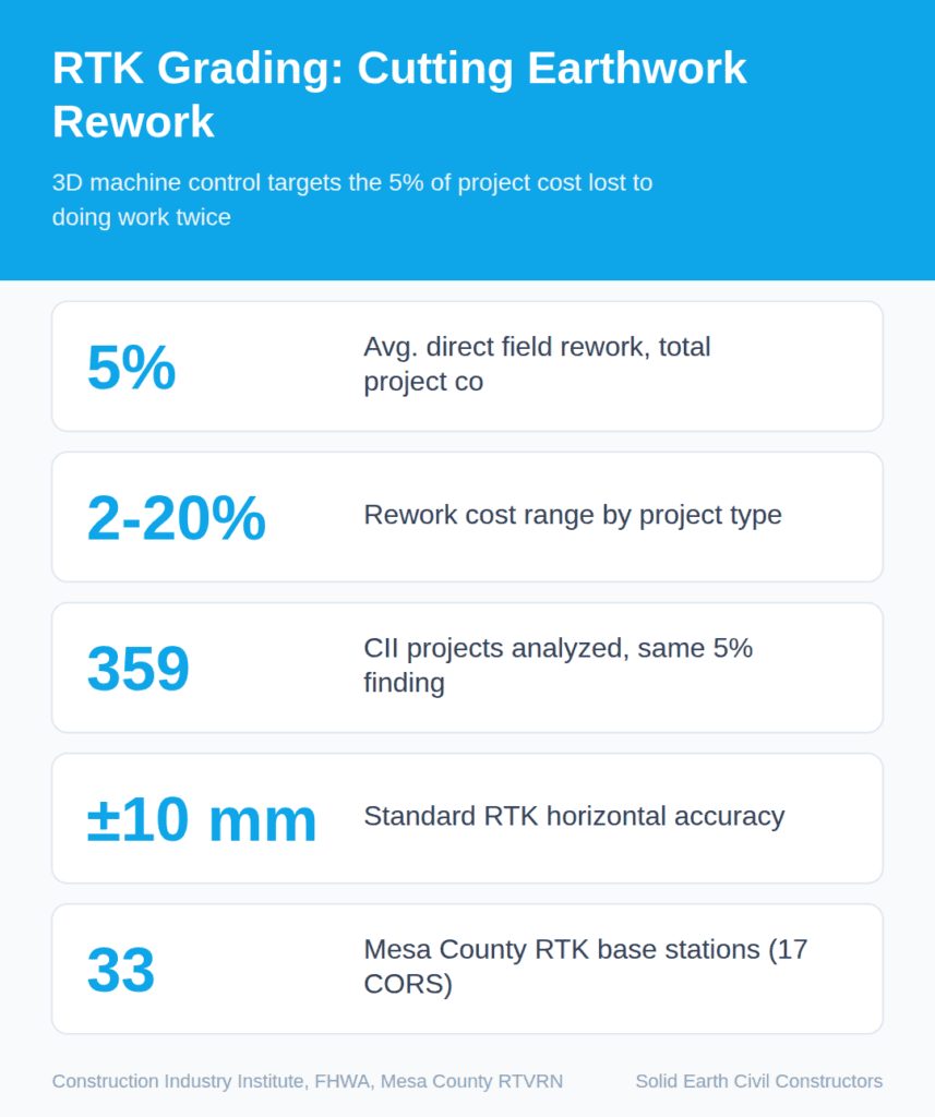
The scale is well documented. The Construction Industry Institute puts direct field rework at an average of about 5% of total project cost, ranging from 2% to 20% depending on project type. An analysis of 359 projects in the CII database found the same figure: direct rework costs alone often total 5% of total construction cost. Broader reviews across regions and project types land in a similar band, with most studies clustering between 4% and 10%.
On earthwork, a large share of that comes from grading to the wrong elevation. That is the target 3D machine control is built to hit.
What “3D machine control” actually means
Start with the analogy. A paper plan tells an operator what the finished ground should look like. Stakes tell them the elevation at a few scattered points. Between those points, the operator is estimating.
3D machine control removes the estimating. The design surface — the full engineered shape of the finished site — is loaded into a display in the cab. Sensors track where the blade or bucket is, in three dimensions, several times per second. The screen shows cut and fill: how far above or below design the cutting edge sits, right now. On automated systems, hydraulics move the blade to design without the operator touching the lever.
The Federal Highway Administration uses the term automated machine guidance (AMG), defined as using data from three-dimensional engineered models to guide construction equipment on a job site. FHWA maintains reference guidance and examples of state DOT specifications for it.

The precise version: the machine knows its own position from satellites, and knows its blade geometry from onboard sensors. Add those together and it knows where the cutting edge is relative to the design model.
How the positioning works, and how accurate it is
Plain satellite GPS is accurate to a few meters. Useless for grading. Machine control uses RTK — Real-Time Kinematic positioning. A base station sits on a known point, compares the satellite signal it receives against the position it knows it occupies, and broadcasts the difference as a correction. The machine (the “rover”) applies that correction and gets centimeter-level accuracy.
Under good conditions — clear sky view and a working correction link — standard RTK delivers roughly ±10 mm horizontal and ±15 to 20 mm vertical accuracy. Independent figures agree on the vertical being the weaker axis: typically 2 to 3 centimeters, generally 1.5 to 2 times the horizontal error.
That matters because grading tolerances are vertical. The good news is that standard RTK accuracy is sufficient for most commercial site grading and residential subdivision work, hitting the ±0.1 foot tolerance called for in most project specifications. Note the word “most.” Concrete subgrade and fine-grade paving tolerances can be tighter than what plain RTK delivers.
Satellites are only half the system. Machine control also relies on inertial measurement units, slope sensors, and rotation sensors mounted on the working components to determine exact blade or bucket orientation. A GPS antenna on the cab roof tells you where the machine is. The sensors tell you where the edge is.
The Colorado variables
Altitude by itself is not the problem. Distance and sky view are.
RTK accuracy degrades as the rover moves away from the base station. The rule of thumb is about 1 part per million — 1 millimeter of added error per kilometer of baseline. The mechanism is atmospheric: the correction assumes base and rover see similar atmospheric conditions, and that assumption weakens as the baseline lengthens. On a linear corridor climbing through mountain terrain, base-to-rover distances grow fast, and the base and the machine may sit in genuinely different air.

Terrain also blocks sky. Canyon walls, deep cuts and heavy timber reduce the number of visible satellites, which is exactly the condition the accuracy figures above exclude.
Colorado does have public correction infrastructure. Available options include the Mesa County Trimble-based network and Plate Boundary Observatory single-baseline stations. The Mesa County Real-Time Virtual Reference Network runs 33 base stations, 17 of them NGS CORS stations, and provides free real-time GNSS corrections on the NAD83 (2011) reference frame. Coverage is regional, not statewide, so the base-station question still has to be answered site by site.
Why it cuts rework
Manual grading verifies elevation at discrete points — wherever a stake or a rod happens to be. Machine control does not. It evaluates the entire working surface in real time, so over-excavation and under-cutting are identified instantly rather than after the fact. The error never becomes a completed pass.
Manufacturers describe the same logic. Caterpillar states that Cat Grade with 3D for Dozers uses automated blade movements to help operators reach the design plan faster, saving time, materials and rework from first pass to finish grade. Industry reporting notes that 2D and 3D grade control significantly reduce rework by enabling precise control over blade elevation and angle.
Reported productivity gains are large: 30% to 50% on rough grading is commonly cited, because operators can see exactly where the high and low spots are. Treat those as reported figures, not guarantees. They come from vendors and practitioners, not controlled trials, and they describe rough grading specifically.
A typical field sequence
- Build the 3D model. Convert the design into a digital surface the machine can read — triangulated surfaces, alignments and reference points.
- Establish the reference frame. Set the site’s coordinate system and datum, and confirm the correction source uses the same one.
- Set or connect a base. Either a site base on a known control point, or a network correction service, keeping baseline distance as short as practical.
- Calibrate the machine. Measure antenna and blade geometry so the system knows where the cutting edge sits relative to the antenna.
- Verify on known control before cutting. Place the blade on a surveyed point and confirm the displayed elevation matches.
- Re-verify through the shift. Repeat the check after moves, restarts or any change in correction source.
What it does not fix
Machine control executes a model. If the model is wrong, it builds the wrong thing efficiently. It also does not remove the need for independent verification — surveyed as-builts remain the check on what the machine believed it was doing. And the accuracy figures quoted here assume clear sky and a live correction link. Lose either, and the system degrades to something the operator must recognize and respond to.
Images are presented for illustration purposes only.We use real photographs when we need to show what was happening at a real event.
About the Author: Solid Earth

Related Posts


Recent Works